
News & FAQ
News
Company news, technical insights and case studies from TAIFU.
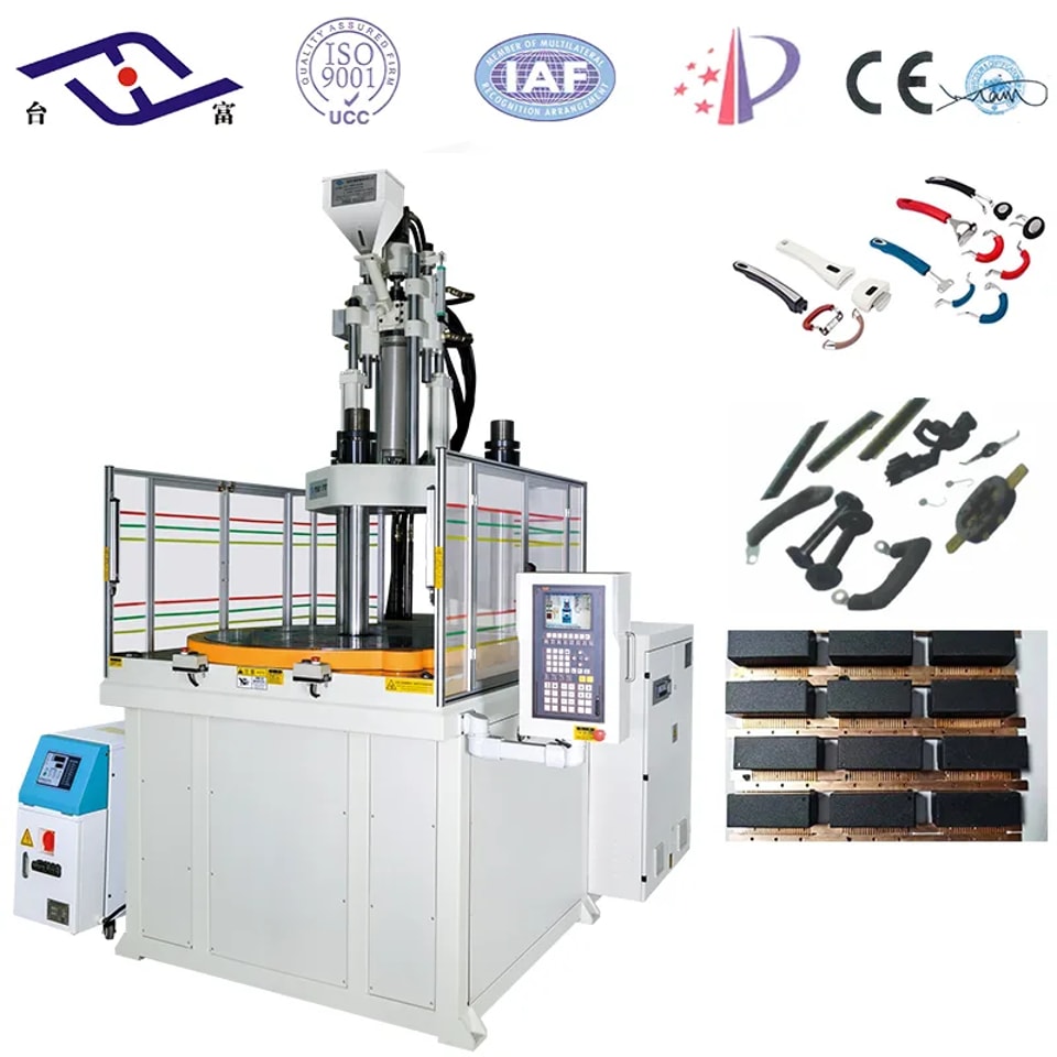
Bakelite is phenol-formaldehyde resin (PF), one of the earliest industrial plastics. It is made from phenols and aldehydes — usually phenol and formaldehyde — by polycondensation with acid or alkaline catalysts. Thermoplastic and thermoset PF Depending on the catalyst, two types of PF are produced: thermoplastic PF, which needs a curing agent plus heat to form a cross-linked structure, and thermoset PF, which cross-links with heat alone. Either way, PF is only usable once cured into a cross-linked network. Curing is an irreversible physical and chemical process — quite different from the melting and solidifying of thermoplastics. Molding PF by injection Injection-grade PF needs good flow, the ability to mold at relatively low pressure, high hot rigidity, fast curing, good surface gloss, easy release and no mold contamination. Limitations include restrictions from filler type, difficulty with parts carrying many inserts, and the fact that cured sprues and runners cannot be recycled. The practical difference Thermoplastic PF can be molded on a standard injection machine with strict process control. Thermoset PF requires a dedicated PF machine — with a barrel and screw different from a standard machine — and molds of a specific design. Taifu builds vertical bakelite machines, BMC machines and standard plastic injection machines. Bakelite and BMC parts are widely used in cookware, electromechanical products and household appliance components.
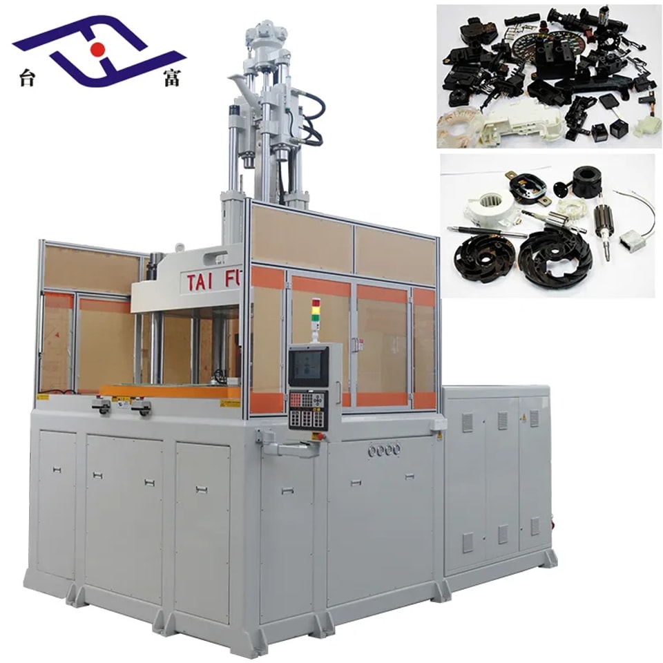
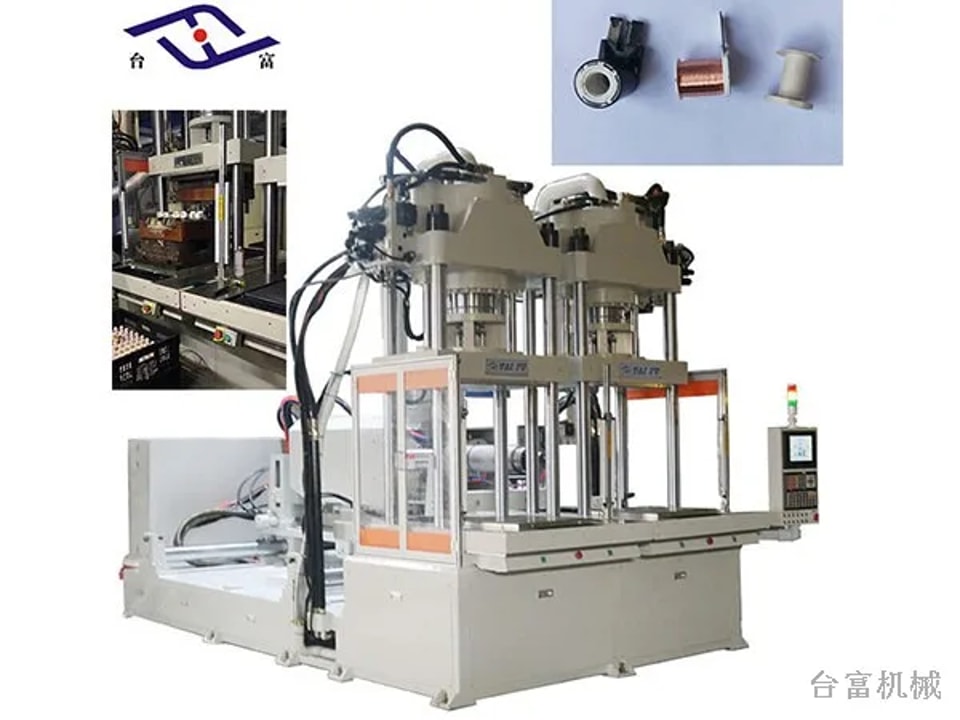
The materials most often used for automotive parts on vertical injection molding machines are PA66+30% GF, PA66, PBT, PP and POM. PA66+30% GF Urea (DEF) tank components, for example, are mainly molded in PA66+30% GF. PA66 stands out in the polyamide family for its high melting point; as a semi-crystalline material it keeps high strength and stiffness even at elevated temperatures. Nylon continues to absorb moisture after molding, and the amount depends on wall thickness and service conditions. When designing precision parts, account for the effect of moisture absorption. Because of the limitations of neat resin, fillers or additives are usually added to improve mechanical properties — most commonly glass-fiber reinforcement, which is why PA66+30% GF is so widely used for automotive parts. Typical parts Vertical machines mold a wide range of automotive and related parts, including fuse box housings, gears, watch cases, scanner housings and Bluetooth accessory housings.
With order volumes rising, coordination between departments had become harder and orders were at risk of being missed. In July 2021 Taifu introduced LED display boards for order management in the workshop, linked to its order management system. Benefits Accurate, real-time order information that reduces repetitive work and saves labor, paper and time. Fewer missed or incorrect orders, with automatic reminders and order status visible at any time. Easy lookup of new and existing customers' orders, so information is not lost when staff change. Order history stored in the cloud and accessible from both PC and mobile, so sales staff can check their orders anywhere. Flexible printing of order information, making accounting checks easier.
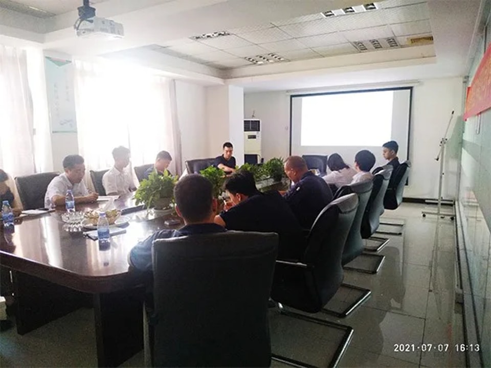
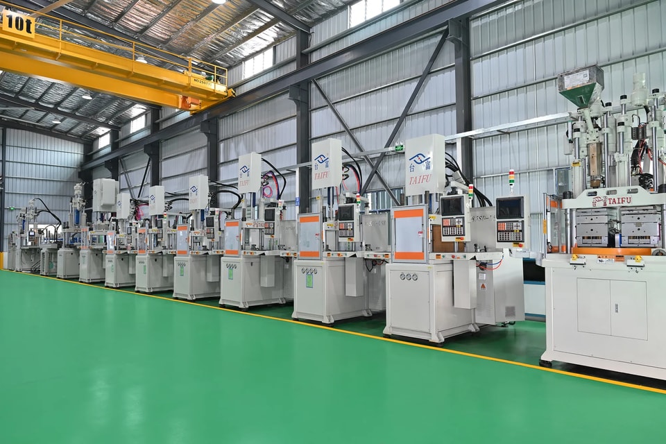
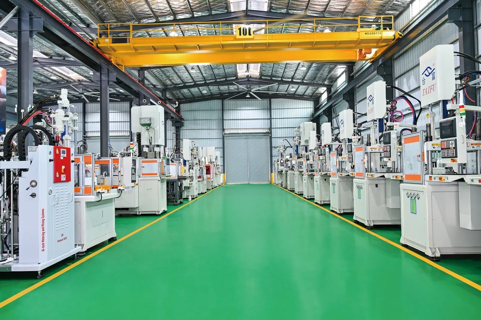
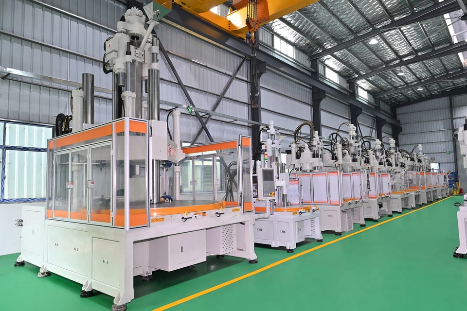
Taifu invited engineers from one of its servo-drive suppliers to give our team in-depth training on their servo systems. With rotating power restrictions in many industrial areas of Guangdong, energy-saving servo systems help customers keep production running while using less power. How dual-servo rotary machines save energy On rotary vertical machines with a dual servo system, both system pressure and flow are closed-loop controlled, and the hydraulic system supplies only the flow and pressure actually needed. This avoids the high-pressure relief losses of a conventional fixed-pump system. During high-flow stages — recovery, clamping and injection — the motor runs at its set speed; during low-flow stages such as holding and cooling, motor speed is reduced. As a result, pump motor energy consumption falls by 40–80%.
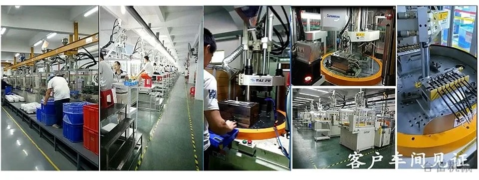
Almost every LCD uses a plastic light guide plate, usually made from highly transparent PMMA or PC. Machines from 55 to 300 tons are used: hydraulic machines for low- to mid-range products, vertical or hybrid electro-hydraulic machines for mid- to high-end products, and all-electric or injection-compression machines for the highest grade. Light guide plates are high-precision optical parts. The printed dot pattern must be complete, the part must not shrink or warp, and the surface must be free of black or yellow specks, gels and contamination, with good overall finish and light transmission. Process requirements (mobile phone light guide plate example) A 120-ton rotary vertical machine can be used. Clamping force must be sufficient and platen parallelism high to prevent flash and keep thickness uniform. Injection must be stable and metering accurate. Shot capacity should not be oversized — too large a shot can yellow the melt. Plasticizing components need a high surface finish to prevent yellowing and black or yellow specks. High injection pressure and speed are required, as PMMA and PC melts flow poorly, especially in thin-wall plates. Because of the high melt viscosity, the screw needs high torque and a design that resists torsional breakage. The mold must fill and release smoothly, be machined to high accuracy and have precise vents. Taifu has supplied 120-ton rotary vertical machines to Fujian a phone-component manufacturer, delivering several hundred rotary machines.
Plasticizing conditions Back pressure. High back pressure gives thorough, uniform plasticizing, but the heat can cause the melt to cure early and lose flow. Low back pressure leaves the material under-plasticized with poor flow. Set it according to the material and the wear condition of the screw and barrel. Screw speed. Too fast shortens plasticizing time and the material is not fully plasticized. Too slow increases friction, overheating the material so that it cures early, releases gas, impairs filling and accelerates screw and barrel wear. Material temperature. Too high and the melt cures rapidly under shear, increasing wear and blocking the nozzle. Too low and plasticizing is insufficient, injection is slow and the cavity does not fill. Generally keep material temperature at 70–90 °C; for PF-161J, 72–78 °C. Filling conditions Injection speed. Too fast generates frictional heat that cures the melt locally or even burns it, trapping moisture and gas and causing pinholes or short shots. Too slow causes flow marks and visible weld lines. Injection pressure. Higher pressure gives good filling and mechanical properties but raises internal stress and thickens flash. Too low pressure causes short shots; repeated short shots can darken the mold release agent and leave the part surface dull and whitish. Hold time. Longer hold increases part weight and density but makes ejection harder; beyond about 25 seconds part weight no longer increases. Shorter hold shortens the cycle but increases shrinkage. Curing conditions Mold temperature. Higher mold temperature shortens the cycle, but too high causes burning, pinholes and gas traps. Too low reduces flow at the melt front, causing incomplete filling, weak bonding, low strength and poor gloss. Curing time. Keep it as short as possible while holding dimensions within tolerance; thicker walls need longer curing. After ejection, parts can cool naturally.
Burned parts are scrap and reduce productivity. Because burns can come from the machine, the mold or the process, the right fix depends on the cause. 1. Machine Abnormal temperature control can overheat the barrel so that material degrades before injection. Material can also hang up in the nozzle, screw flights or check valve, degrade and then be carried into the part as dark brown burn streaks. Remove and clean the nozzle, screw and barrel. 2. Mold Poor venting is the main cause. These burns usually appear at the same fixed location on the part, which distinguishes them from machine-related burns. Add vents or venting ejector pins. 3. Contaminated material Dust or debris in the resin can burn. Take care when loading material, and fit a magnetic grate on the hopper to catch metal particles. 4. Process settings Excessive back pressure can overheat the barrel and cause burns. Screw speed that is too high also generates excess heat; 40–90 rpm is generally appropriate. Where the mold has no vents or only small ones, high injection speed can cause burns from compressed hot gas.
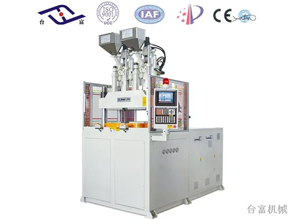
Injection pressure Choose injection pressure according to part shape and wall thickness and the material being molded. Where production conditions and quality standards allow, a lower-temperature, lower-pressure process is recommended. Back pressure Back pressure — also called plasticizing pressure — is the pressure the material is under during plasticizing. Higher back pressure improves color mixing. It helps expel gases from the melt, reducing silver streaks and bubbles. Appropriate back pressure prevents material hanging up in the barrel, which is why back pressure is often increased when purging. Injection speed Low-speed filling gives a steady flow, stable dimensions with little variation, and low, uniform internal stress. Its drawbacks are weld lines, delamination and flow marks. High-speed filling allows lower injection pressure, improves gloss and smoothness, eliminates weld lines and delamination, reduces sink marks and gives more uniform color. Its drawbacks are jetting (hesitation or turbulence), excessive temperature rise and yellowing, poor venting and occasionally difficult ejection. With high-viscosity materials, melt fracture can occur, causing surface haze and increasing the tendency to warp from internal stress and to crack along weld lines in thick parts.
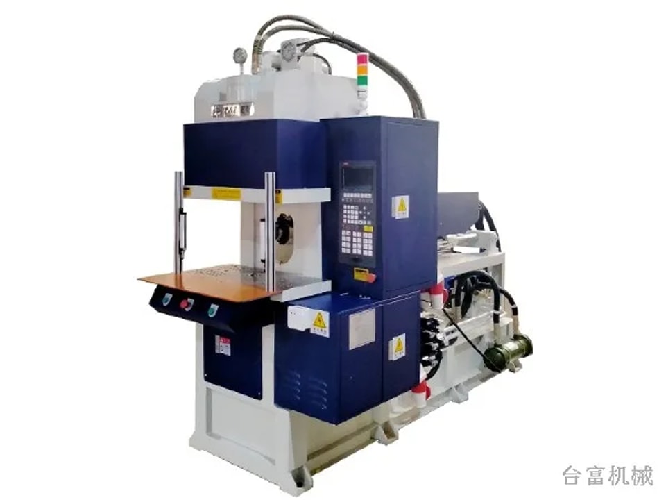
Injection pressure The pressure actually applied during injection is higher than the pressure needed to fill the cavity. Cavity pressure rises sharply to a peak, and that peak is what is usually called injection pressure. Holding pressure After the cavity is filled and until the gate has frozen, the plastic in the cavity still needs substantial pressure — this is holding pressure. It: Packs additional material near the gate and prevents unsolidified material from flowing back toward the gate under residual pressure before the gate freezes. Prevents shrinkage and sink marks and reduces voids. Reduces sticking, cracking or warping caused by excessive injection pressure. Holding pressure is therefore usually set at 50–60% of injection pressure. If holding pressure is too high or held too long, cold material from the gate and runner can be pushed into the part, leaving bright cold-slug marks near the gate and needlessly lengthening the cycle.
Request a machine proposal
Enquiry about

© 2026 Dongguan Taifu Machinery Co., Ltd.