
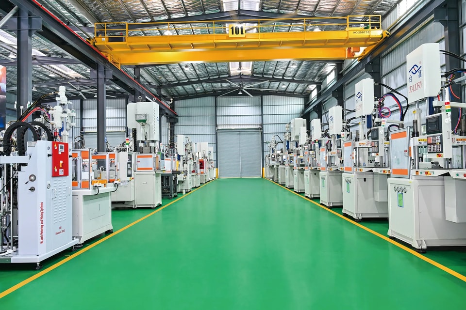
Custom engineering
From your part to a machine built for it.
Submit the part, material and mold. We propose the machine, test it with your mold and deliver it ready to run.
How it works
Four steps, one engineering team
Send your part
Drawing or sample, insert details, material, number of cavities and annual volume.
Machine proposal
We propose the table type, clamping force, stations, injection unit and options, with a quotation.
Testing
Your mold is trialed on the machine at our plant; settings are recorded and preset.
Delivery
Packing, shipment, installation guidance and operator training.
Selection tool
Estimate clamping force and shot size
A first estimate from our selection guide: clamping force = material constant × projected area. Our engineers confirm the final figures.
0tons clamping force
- Projected area
- –
- Clamping force range
- –
- Shot weight per cycle
- –
Selection guide
Seven checks before you choose a machine
Our engineers run these checks on every enquiry. Knowing them helps you send the right information — and compare machines on the points that matter.
First, collect
- Mold dimensions (L × W × H), weight and special design features; guide-pin stroke; whether there is a hot runner and ejector system.
- Properties of the plastic material.
- Size and weight of the molded part.
- Molding requirements: number of cavities, cycle time, quality, appearance and dimensional tolerances.
- Right typeChoose the machine type and series from the part and the material.
- Mold fitsCheck tie-bar spacing and minimum mold height against the mold size.
- Part comes outCheck maximum opening stroke and ejector stroke against the mold and the part.
- Clamps tightEstimate the clamping force from the material and the projected cavity area.
Clamping force (t) = clamping constant (t/cm²) × projected area (cm²) - Shot is fullChoose shot size and screw diameter from the part weight.
Shot weight (g) = density (g/cm³) × injection volume (cm³) × 85% - Molds wellCheck screw L/D ratio and injection pressure against the material.
- Fast enoughCheck injection speed through the injection rate.
Injection rate (cm³/s) = 0.785 × screw diameter² (cm²) × injection speed (cm/s)
Rules of thumb
- Shot capacity is the measured weight at full injection stroke; convert it using the density of your material.
- The actual shot should ideally be 30%-80% of maximum shot capacity. Avoid a screw that only just meets the requirement - once it wears, part quality drops.
- Do not increase shot size by extending the metering stroke. Beyond 3-5 × screw diameter, melt homogeneity suffers and air may be drawn into the melt, causing surface defects.
- Do not choose a machine that is too large for the mold. A small mold on large platens increases platen and tie-bar deflection and can lead to fatigue failure; the mold should be at least 2/3 of the tie-bar spacing.
- Understand injection rate vs. plasticizing capacity: injection rate governs the injection phase, plasticizing capacity governs screw recovery; together they set the minimum cycle time.
- Understand injection pressure vs. clamping force: clamping force must exceed cavity pressure × projected area, so estimating from cavity pressure gives a realistic requirement.
Screw selection
ABS, PC+ABS, PS, PP, PE, POM, black PCsoft PVC, TPU, TPE, TPR, PU, TPC
LCP, PA, PA6, PA66, PA6T, PCPPS, PBT, PPO, PEEK
for PC, PMMA, optical lenses and light-guide platesensures excellent clarity and surface finish with long service life
for PA or PE with color masterbatch and other materials requiring intensive mixingsolves uneven coloring and feed slippage
Clamping constants by material t/cm²
| Material | Constant |
|---|---|
| PS (GPPS) | 0.155–0.31 |
| HIPS | 0.155–0.31 |
| ABS | 0.388–0.62 |
| PS (GPPS) thin-wall | 0.465–0.62 |
| HIPS thin-wall | 0.388–0.543 |
| LDPE | 0.155–0.31 |
| AS (SAN) | 0.388–0.465 |
| PP (homo/co-polymer) | 0.233–0.388 |
| HDPE | 0.233–0.388 |
| AS (SAN) long flow | 0.465–0.62 |
| PP long flow | 0.388–0.543 |
| HDPE long flow | 0.388–0.543 |
| PPVC | 0.233–0.388 |
| PA6/PA66 | 0.62–0.775 |
| PMMA | 0.31–0.62 |
| UPVC | 0.31–0.465 |
| PC | 0.465–0.775 |
| POM (homo/co-polymer) | 0.465–0.775 |
| PET (amorphous) | 0.31–0.388 |
| PET (crystalline) | 0.62–0.693 |
| PBT | 0.465–0.62 |
| CA | 0.155–0.31 |
| PPO-M (unreinforced) | 0.31–0.465 |
| PPO-M (reinforced) | 0.62–0.775 |
| PPS | 0.31–0.465 |
Material densities g/cm³
| Material | Density |
|---|---|
| GPPS (PS) General-purpose polystyrene | 1.04–1.09 |
| PPS Polyphenylene sulfide | 1.28–1.32 |
| ABS Acrylonitrile butadiene styrene | 1.01–1.08 |
| HIPS High-impact polystyrene | 1.14–1.20 |
| AS (SAN) Styrene acrylonitrile | 1.06–1.10 |
| LDPE Low-density polyethylene | 0.89–0.93 |
| PP Polypropylene | 0.85–0.92 |
| HDPE High-density polyethylene | 0.94–0.98 |
| PPVC Plasticized PVC (soft) | 1.19–1.35 |
| PA-6 Nylon 6 | 1.12–1.15 |
| UPVC Rigid PVC | 1.38–1.41 |
| PA-66 Nylon 66 | 1.13–1.16 |
| PMMA Acrylic | 1.16–1.20 |
| POM Polyoxymethylene | 1.41–1.43 |
| PC Polycarbonate | 1.20–1.22 |
| CA Cellulose acetate | 1.25–1.35 |
| PET Polyethylene terephthalate | 1.29–1.41 |
| PPO-M Modified polyphenylene oxide | 1.04–1.10 |
| PBT Polybutylene terephthalate | 1.30–1.38 |
Selection & resources
Everything around the machine
Selecting the machine is the start. We also connect the mold, material, peripherals and automation for a complete cell.
Molds
We coordinate with mold makers experienced in vertical and insert molding. Check the mold against tie-bar spacing, mold height and opening stroke — the mold should cover at least two-thirds of the tie-bar spacing to avoid platen deflection.
Materials
The screw is matched to the resin: general-purpose for ABS, PP, PE and POM; bimetallic for PA, PC, PBT, PPS and LCP; chrome-plated for clear PC and PMMA; high-mixing for color masterbatch. Thermoset bakelite and BMC need dedicated injection units.
Peripheral equipment
Granulators, gravimetric blenders, mold temperature controllers and hopper dryers from partner brands can be sourced and shipped together with your machine.
- Centralized Granulators
- Gravimetric Blender
- Oil-Type Mold Temperature Controller
- Energy-Efficient Hopper Dryer (SEHD)
Automation
Take-out robots, insert loading and conveyors integrated with rotary and sliding tables. A robot keeps the cycle constant, protects the mold if a part fails to drop and lets one operator supervise several machines.
Payment & leasing
Ask about flexible payment arrangements for your order. Leasing depends on your country and is confirmed case by case.
Contact & RFQ
Tell us what you are molding
Part drawing, insert, material and volume are enough to start. We reply with a machine proposal.
Request a machine proposal
Enquiry about

© 2026 Dongguan Taifu Machinery Co., Ltd.