
News & FAQ
Technical Insights
A vertical machine's hydraulic drive transmits power and signals through pressurized oil, so the condition of the oil and seals directly affects system stability and, indirectly, part quality. About half of hydraulic failures are caused by incorrect use or maintenance of the oil, so good maintenance habits are the most effective way to prevent them. Key properties The most important properties of hydraulic oil are viscosity and cleanliness, along with resistance to oxidation, wear, foaming and corrosion, and good lubricity. Viscosity is expressed as the average kinematic viscosity at 40 °C. Commonly used ISO VG 46 anti-wear hydraulic oil has an average kinematic viscosity of 46 cSt at 40 °C. Viscosity falls as temperature rises and increases as pressure rises. Test regularly Contaminated or degraded oil shortens pump life and can cause failures, so test the oil periodically and use the results to decide when to change it. Three quick checks: Appearance test. Put samples of new and used oil into separate test tubes and compare color, clarity, floating particles and any water at the bottom. Blotter test. Drop used oil onto filter paper and examine it after one hour. Dirty or degraded oil shows contaminants clearly. Finger test. Rub used oil between your fingers. If viscosity has dropped, it feels rough rather than slick, and drips off freely without a sticky, elastic feel.
Machine requirements for LCP Screw made from highly wear-resistant material Screw tip with an anti-backflow (check) structure Precise temperature control system Specially designed nozzle Responsive feeding and injection systems Barrel capacity matched to part weight — neither too large nor too small Mold guidelines Mold design is critical. Use a standard open (cold) gate rather than a hot nozzle; hot nozzles tend to overheat LCP and cause blistering. Mold temperature is typically around 140 °C. Keep the upper (fixed) half hotter than the lower (moving) half: the hotter fixed half keeps the melt flowing and avoids cold slugs, while the cooler moving half helps the part crystallize. Keep the difference within 15 °C. Choose a lower mold temperature to shorten the cycle and prevent flash; choose a higher one when dimensional stability is critical or to reduce weld lines and short shots. Pressure and speed The right pressure depends on the material, part geometry, mold design (especially sprue, runners and gates) and other conditions. All LCP grades have very low melt viscosity, so pressures are lower than for typical thermoplastics. Start with low pressure and increase gradually; most parts mold at 15–45 MPa. LCP solidifies quickly, so high injection speed generally gives good results. Cycle time Thanks to LCP's good flow and fast solidification, fill times and cycles are short — typically 10–30 seconds, depending on part size, shape, wall thickness, mold and conditions.
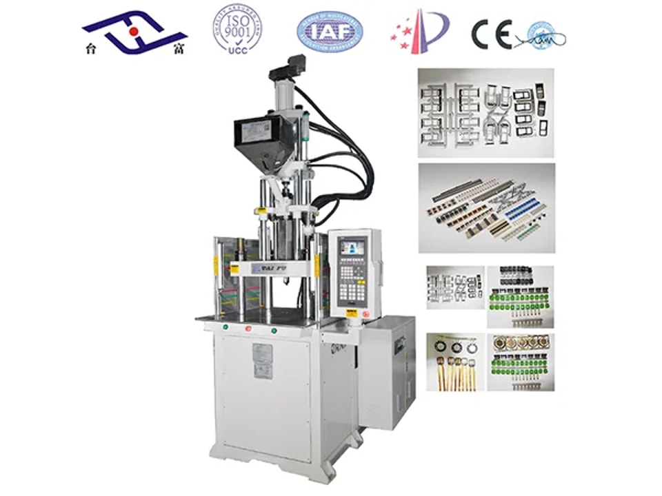
Vertical injection molding machines come in several types: fixed-table, single sliding table, double sliding table, rotary table, C-frame, two-color, thermoset BMC and vertical silicone machines. For newcomers to insert molding, here is how typical products map to machine types. Fixed-table vertical machine: connectors, USB cables, light strings, data cable overmolding, power cord plugs, network and TV power plugs. Single sliding table: inserts without cables, such as keys, buckle overmolding, plastic hangers and overmolded spoons. Double sliding table: cable-free parts for computers and telecoms, bag buckles and cosmetic bottle connectors. Rotary table: LED lamp caps, small toys and automotive electronic parts. C-frame: waterproof switches, charging cables and electrical wires. Two-color machine: toothbrush handles, baby products and two-color sporting goods. Thermoset BMC machine: cookware handles and high-voltage electrical handles. Vertical silicone machine: baby bottle nipples, teethers, silicone tubing, gloves, seals, pot holders, coasters, diving masks and other silicone, medical and baby products.
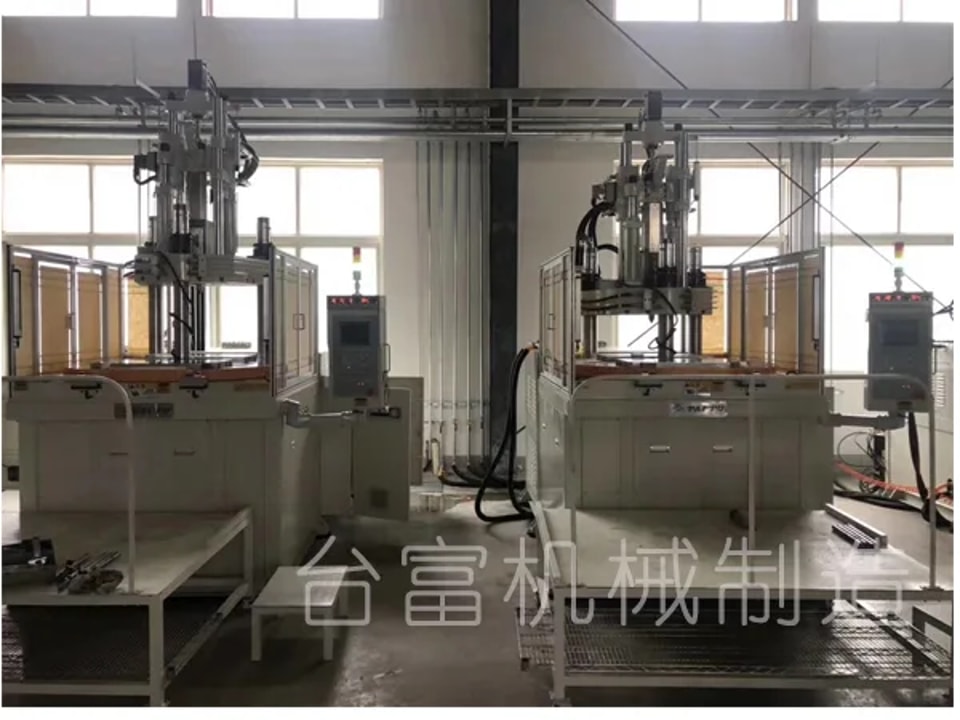
Overmolding on a vertical machine gives products a soft-touch surface and adds both function and value. Over the past decade it has changed aesthetic standards, design thinking and functional requirements for consumer goods, and medical device makers are increasingly using it as well. Beyond soft-touch surfaces, overmolding supports ergonomic design, two-color appearance, brand marking and improved properties. It can add functions such as noise reduction, vibration damping, waterproofing and impact protection. Like co-injection, two-shot and sandwich molding, overmolding is a multi-material molding technology: two or more materials with different properties are combined to increase product value.
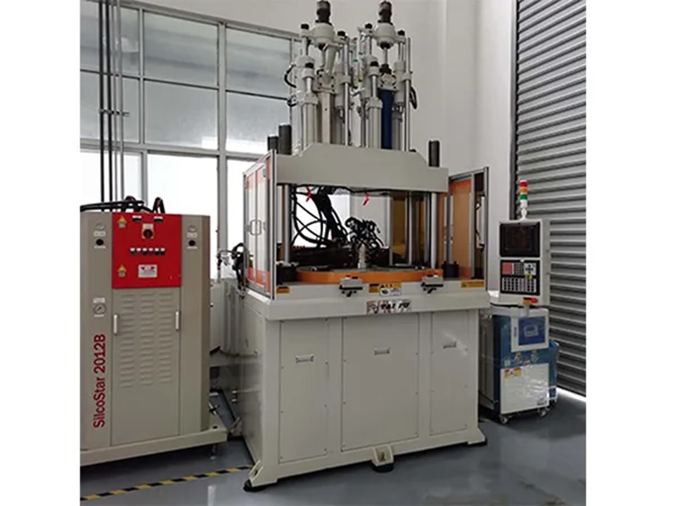
Two-color vertical machines mold two different plastics into one part on the same machine — most commonly a hard substrate overmolded with a soft material using a rotating table. Material guidelines The two materials must have a clear difference in melting temperature: 60 °C is recommended, and at least 30 °C. The first shot should be the material with the higher melting point — typically PC or PC/ABS. The second shot is typically TPU or TPE. Typical thicknesses: PC substrate 0.6–0.7 mm, soft layer 0.4 mm or more. Improving adhesion Make the contact area as large as possible and add grooves to increase bonding. Alternatively, use a core-pull on the first shot so that part of the second-shot material flows into the first-shot part. Keep the mold surface for the first shot as rough as possible.
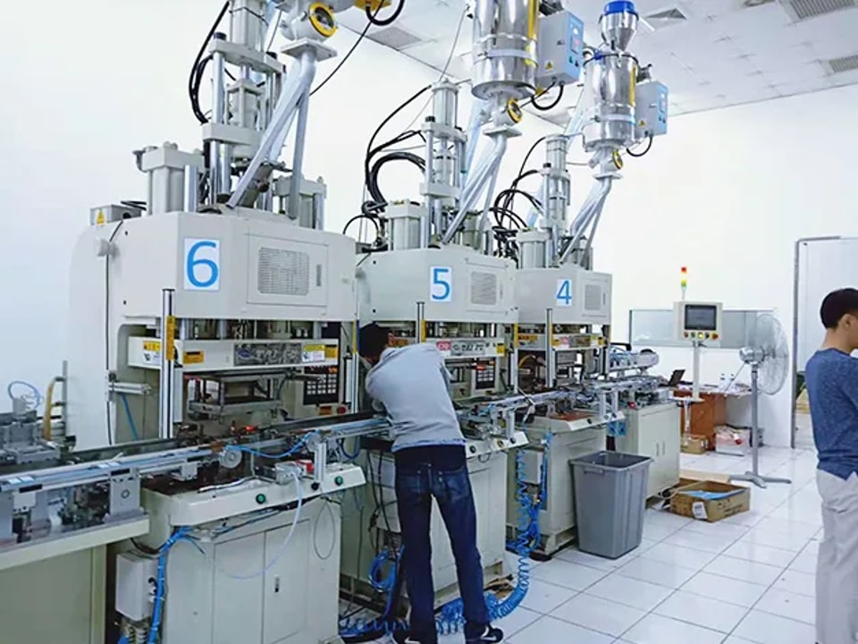
Vertical injection molding is now used for everything from baby and household products and consumer electronics to irregular components, automotive parts and power cables. One of the most common issues our after-sales engineers are asked about is excessive flash. Insufficient clamping force: check clamping force against the mold structure and size and make sure it is sufficient. Shot volume too large: reduce shot volume. Injection pressure too high: lower injection pressure. Mold temperature too low: raise mold temperature. Insufficient mold machining accuracy: inspect and analyze the mold. Material viscosity too low or curing too slow: increase material viscosity or speed up curing. Work through these causes one by one to find the root cause. Short shots are the opposite problem and are analyzed in the opposite direction. In one case, working together with the customer's process engineers, our after-sales team brought the yield on a vertical machine to 98.6%.
Vertical injection molding machines vary widely in size, specification and quality. Select a machine based on the size and quality requirements of your parts, and on both current and long-term needs. Start by defining the part's function, material, volume, shot weight and annual output. A plant molding silicone, for instance, should approach selection differently from one molding engineering plastics. Then check the following specifications. Shot volume Shot volume is normally rated for PS (polystyrene). If your material is not PS, convert the rated figure using the density of your material before comparing it with your part weight. Clamping force Clamping force is the final locking force the platens exert on the mold while melt is injected into the cavity. Without enough clamping force the part will flash, so make sure the force your part requires is below the machine's rating. Required clamping force is usually calculated as average cavity pressure multiplied by the projected area of the cavity. Average cavity pressure is generally 20–40 MPa, depending on the material, part requirements and flow-length ratio. During mold design, computer simulation can give an accurate clamping force.
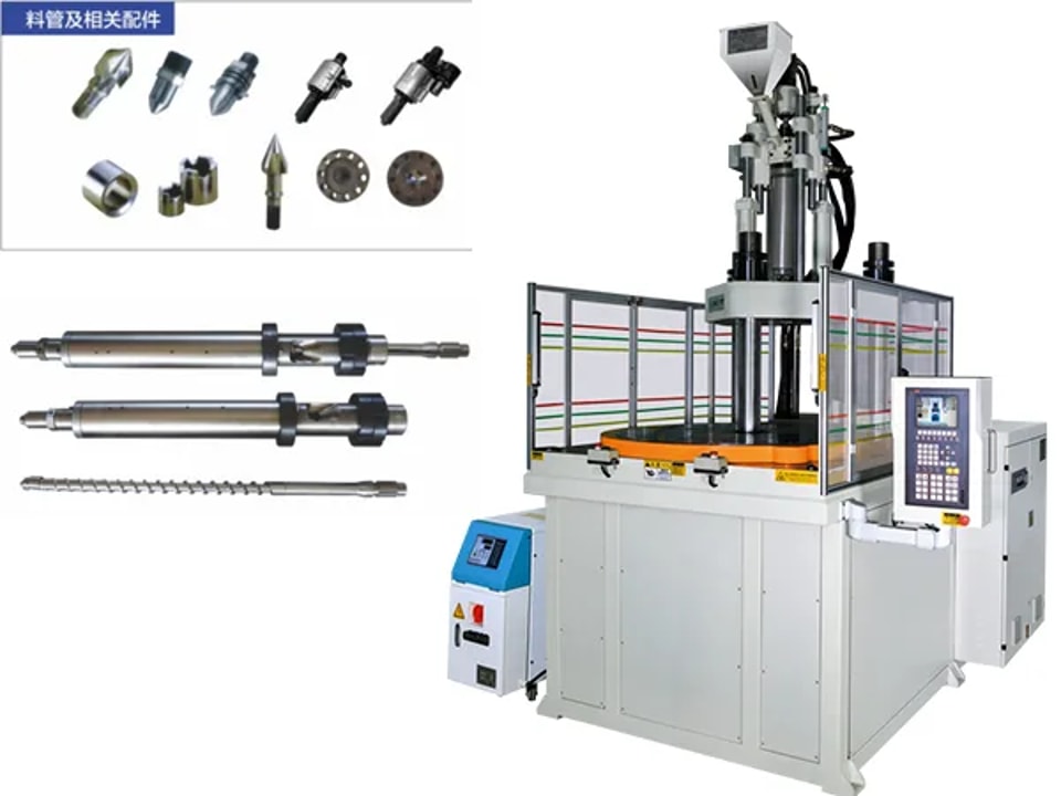
One common reason for unstable production on a vertical machine is screw slippage. The screw tip assembly The screw tip assembly has three parts: the screw tip, the check ring and the check ring seat. Together they seal, mix and plasticize the material. Many part quality problems are closely linked to these components, and small issues here can sharply raise scrap rates or even force a shutdown for repair. What slippage looks like During recovery, the screw rotates and retracts to convey material for the next shot. Slippage occurs when the screw keeps rotating but stops moving axially. Material may build up at the feed throat instead of being conveyed forward. Slippage tends to degrade the material before injection, reduces part quality (for example short shots) and lengthens the cycle. Quick checks Purge with a small amount of material from the rear of the barrel and check melt temperature. With short residence time, melt temperature will be lower than the barrel setting. Inspect molded parts: marbling, black specks or faint streaks show the material is not being properly mixed in the barrel. Fixes Gradually raise the feed-zone temperature until screw rotation and retraction are synchronized. Sometimes the barrel must be set above the recommended temperature to reach this point. Check back pressure. If it is set too high, the screw cannot generate enough forward melt pressure to overcome it and will rotate in place without retracting — adding work and heat to the melt and hurting part quality and cycle time. Back pressure is adjusted with the control valve on the injection unit.
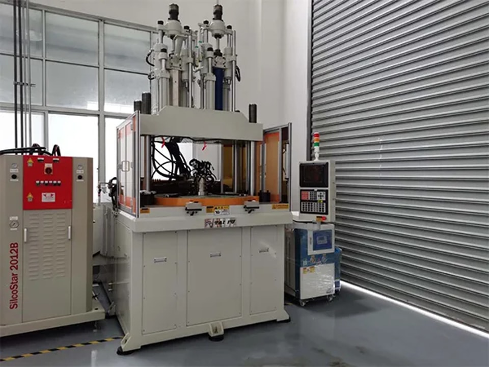
Customers often ask whether they need a liquid silicone (LSR) injection machine or solid silicone equipment. Here is how to tell the two apart. Appearance LSR parts are highly transparent and odorless, with a visible injection gate and no obvious parting-line flash. Solid silicone parts are less transparent, may smell of curing agent, have no injection gate, and show a parting line where the upper and lower molds meet. Applications LSR: baby products, kitchenware and medical products — items that come into direct contact with food and the body. Solid silicone: daily-use goods, industrial parts, waterproof seals for electronics and automotive components. Material safety LSR is a highly transparent, high-safety material; no curing agent or other additives are added during molding. Solid silicone requires a curing agent to speed up vulcanization, demolding and feeding. Molding process LSR is vulcanized in an injection molding machine. The process is simple, accurate and productive, and saves labor, power and material. Solid silicone is mixed, cut to size and placed into the mold, then formed in a compression press at a set temperature, with mold cleaning required after demolding. Tooling Solid silicone molds are relatively simple and inexpensive — a cavity machined to the part's dimensions. LSR molds are more complex: gate location, cold runner system, venting and mold temperature monitoring must all be designed in, so tooling costs more.
Request a machine proposal
Enquiry about

© 2026 Dongguan Taifu Machinery Co., Ltd.