
News & FAQ
Technical Insights
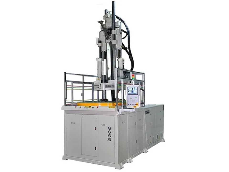
Screw size determines how much material a rotary vertical machine can inject per shot, so choosing the right screw directly affects part quality. Screw too large for a light part: excessive melt volume and residence time tend to burn or yellow the part. Screw too small for a heavy part: the part is likely to be short-shot and fail to meet design requirements. Mold design causes of incomplete filling Over-complex molds with many turns, poorly placed gates, narrow runners, too few gates or the wrong gate type. Very thin local sections: increase wall thickness overall or locally, or add an auxiliary runner or gate near the unfilled area. Inadequate venting: short shots often occur at corners, deep recesses, thin sections surrounded by thick walls, and the bottoms of thin housings molded with side gates. Add effective vents, position gates so air is pushed out first, and where necessary make the trapped-air area a separate insert so air can escape through the gap. Unbalanced filling in multi-cavity molds: reduce the number of cavities if needed to keep the remaining parts within specification.
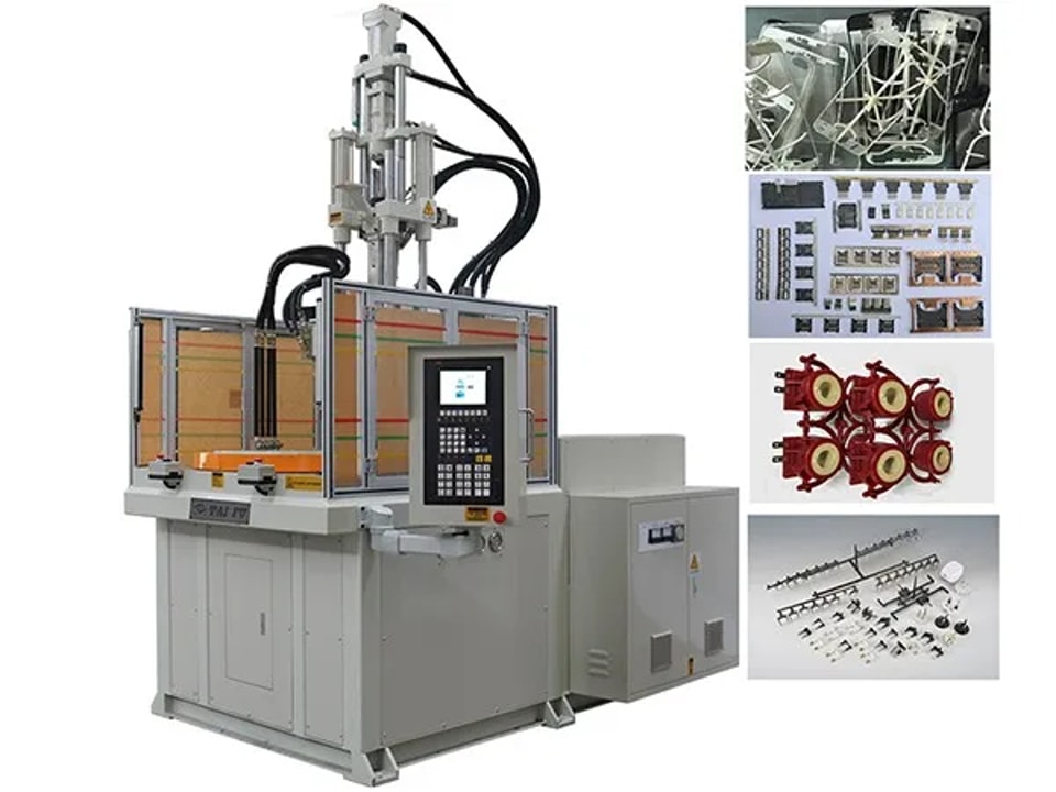
Proportional control The hydraulic system needs proportional pressure and flow valves, or a closed-loop variable pump system, to provide different working pressures and flows. Whether the pump is fixed- or variable-displacement, proportional valves control pump output pressure and flow with linear adjustment. Separate clamp and injection circuits On direct-pressure clamping machines, injection begins the instant high clamp pressure is built, while oil is still filling the clamp cylinder. If the two circuits were shared, the moving platen could be pushed back by fill pressure and mold-opening force, the pump could overload, and injection speed and stability would suffer. The clamp and injection circuits must therefore be separated. Fast response for high-speed molding High-speed vertical machines often mold at high injection pressure and speed — for connectors or keypads, for example — with fill times of only a few tenths of a second. The system must respond quickly; otherwise output lags the command signal, process setting becomes difficult and part dimensions and weight become unstable. Response depends on controller scan time, pump response and valve response. Systems with servo valves have a clear advantage in response and repeatability. On variable-pump machines, pressure and flow are adjusted by the pump swashplate angle, giving fast response and pump repeatability better than 0.2%. Mechanical, electrical, hydraulic and instrumentation integration Modern machines are fully computer-controlled, with operator dialog, fault self-diagnosis, process monitoring and SPC quality monitoring. The hydraulic system powers every movement, the controller manages it, and instruments monitor machine status — and a robot can be added for automated operation.
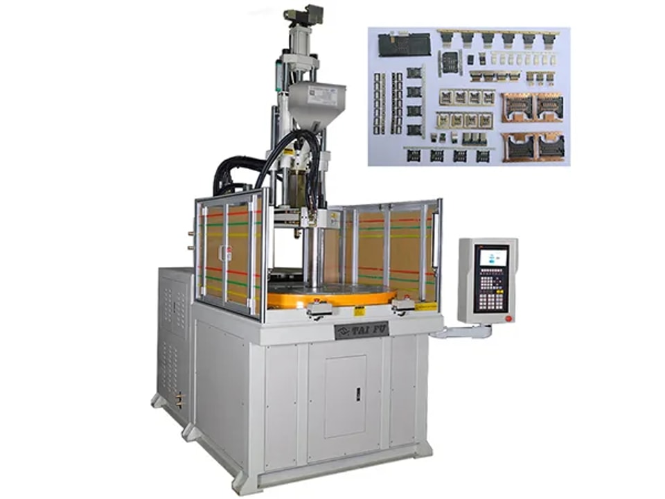
Thin-wall parts include connectors, waterproof plugs, eyewear nose pads, buttons, tags, overmolded shoe studs and small parts for clocks and cameras. How should you judge a high-speed vertical machine for this work? Repeatability Two measures are commonly used: repeatability of part dimensions and repeatability of part weight. Dimensions are hard to compare between parts of different size and thickness, so shot-weight repeatability is the better indicator of overall machine performance. A standard vertical machine typically repeats to around 1% by weight; a better machine reaches about 0.8%. Dimensional tolerances for such parts are often within 0.01–0.001 mm. Injection pressure Standard machines: 147–177 MPa High-speed precision machines: 216–243 MPa Ultra-high-pressure machines: above 243 MPa, typically 243–392 MPa Higher injection pressure brings three benefits: Better precision. Injection pressure has a marked effect on molding shrinkage; at around 392 MPa, shrinkage approaches zero and part accuracy depends mainly on the mold and environment. Tests show that raising injection pressure from 98 to 392 MPa can increase mechanical strength by 3–33%. Thinner walls and longer flow. With PC, a standard machine at 177 MPa can mold walls of about 0.8 mm, while 392 MPa allows walls down to about 0.45 mm and a higher flow-length ratio. Full use of injection rate. Rated injection rate is reached either by raising system pressure or by modifying the injection unit, including screw parameters. Injection speed High-speed vertical machines need high injection speed: above 200 mm/s for hydraulic machines and above 300 mm/s for all-electric machines.
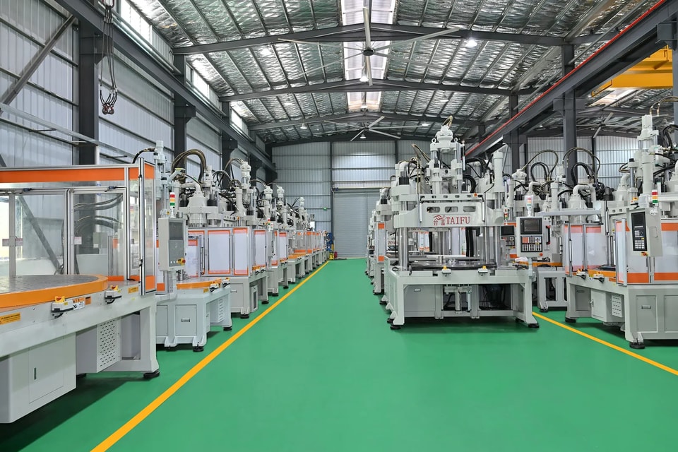
Shot volume Shot volume is a key performance figure that indicates the weight of part the machine can produce. Depending on definition, it is expressed as theoretical shot volume, theoretical shot weight or actual shot weight. It is determined by screw diameter and stroke. Injection pressure The pressure the screw applies to the material during injection. It overcomes flow resistance from barrel to cavity, gives the melt the necessary speed and packs it. It is closely linked to part quality and dimensional accuracy, and is influenced by the plastic, the screw design and the processing temperature. Flow length and part weight increase with pressure, while shrinkage in the flow direction decreases. Injection rate To obtain parts with uniform density and stable dimensions, the cavity must be filled in a short time. Injection rate is the mass of melt injected from the nozzle per unit time. It is proportional to screw travel speed and inversely proportional to injection time, and can be calculated from screw diameter, injection speed, stroke and injection time. Injection power Power demand varies greatly across the cycle. The hydraulic system's peak power occurs during injection and is determined by injection speed and injection pressure. Plasticizing capacity and recovery Plasticizing capacity is the amount of plastic the injection unit can melt uniformly per unit time at maximum screw speed and zero back pressure. It depends on screw diameter, L/D ratio, screw speed and the material, and is governed mainly by the conveying capacity of the metering zone. Screw recovery time should be shorter than the part's cooling time; otherwise the cycle is extended.
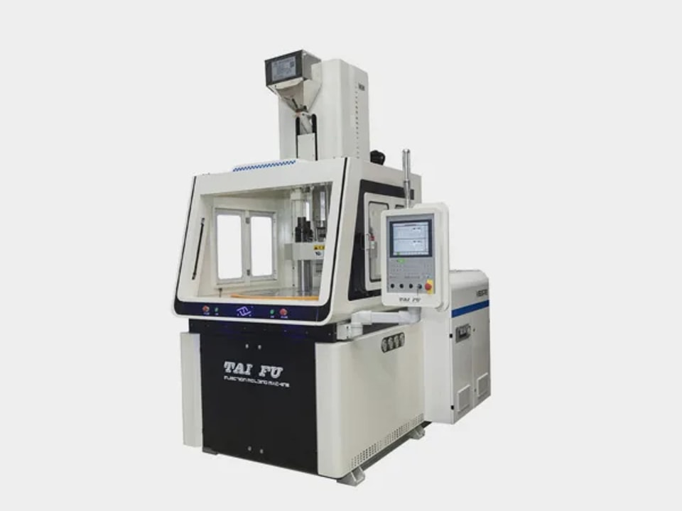
Know the mold's condition Test mold performance under normal operation and measure the final molded parts. This tells you the current state of the mold and helps locate damage to cavities, cores, the cooling system and parting surfaces. Ejector and guide components These ensure the mold opens and closes and parts are ejected. If any of them seizes, production stops. Lubricate ejector pins and guide pillars regularly and inspect them for deformation and surface damage, replacing them promptly when needed. After each production run Apply mold rust-preventive oil to working surfaces, moving parts and guides. Pay particular attention to the spring strength of bearing parts in gear, unscrewing and spring-loaded molds. Clean the cooling channels. Scale, rust, sludge and algae narrow the channels over time, reducing heat exchange and raising production costs. Hot runner molds At the end of each production cycle, measure band heaters, cartridge heaters, heating probes and thermocouples. Replace any damaged parts, compare readings with the mold's history and keep records so problems are caught early. Surface care Mold surfaces directly affect part appearance, and rust prevention is the priority, so choose a suitable rust-preventive oil. Remove residues after production using copper rods, copper wire and mold cleaner, then dry the mold. Never use steel wire or steel rods, which scratch the surface. If corrosive materials have caused rust, grind and polish, apply rust-preventive oil and store the mold in a dry, cool, dust-free place.
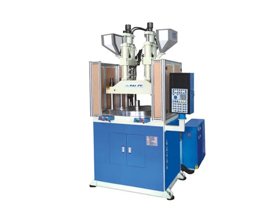
Vertical injection molding machines are widely used in automotive, electronics and medical manufacturing. Here is how they differ from horizontal machines. Automation through the mold. Conveyor or strip-feed systems can easily pass through the middle of the mold, making automated production straightforward. Consistent flow and mold temperature. The vertical layout helps keep resin flow and mold temperature distribution uniform. Insert molding. With the mold face pointing up, inserts are easy to place and stay in position. On machines with a fixed lower platen and moving upper platen, combining a conveyor with a robot allows fully automatic insert molding. (Modern horizontal machines can also insert-mold well, so the gap here has narrowed.) Open clamping area. The clamp is usually open on all sides, making it easy to add automation for complex, delicate parts. Table options. Rotary tables, sliding tables and tilting tables make insert molding and in-mold assembly easier. Low-cost trial runs. For small-batch trials, molds are simple, inexpensive and quick to mount and remove. Long-term accuracy. The mold weight rests on the horizontal platen, so there is none of the forward sagging caused by mold weight on horizontal machines. This helps preserve machine and mold accuracy over time.
Request a machine proposal
Enquiry about

© 2026 Dongguan Taifu Machinery Co., Ltd.